| Receive
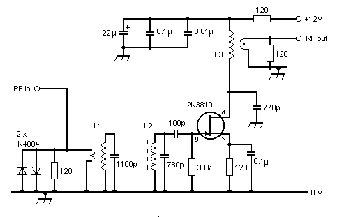
Pre-selector for 136 kHz This pre-selector can be used to increase both the gain and the RF selectivity of an LF receiving system. This circuit is lilely to improve considerably the reception of LF signals when using one of the modern 'general coverage' receivers, as such equipment often performs poorly below 500 kHz. A gain of about 14 dB can be expected.
FIGURE 1 - Circuit diagram of Receive Pre-selector
L3 was wound on a 25 mm OD 3C85 ring core: 36 turns on the primary; 4 turns on the secondary, using wire obtained from stripped-down internal telephone cable (the wire is plastic coated with a conductor size of 0.020 inch - 25 SWG, or about 24 AWG). During construction, L1; L2; and L3 were initially resonated to 136 kHz using a variable capacitor to determine the required value of fixed capacitors. Magnetic coupling is used between L1 and L2 by mounting the two ferrite rod cores in parallelism, at a centre-to-centre spacing of 30 mm. If you don't have any old long wave coils in the junk box (and you can't bear to strip down that favourite transistor radio from the 1960s), there are lots of other possibilities. Any coils in the 1 to 3 mH range should resonate just fine. The coils used for bias oscillators in VCRs and audio tape recorders would work well, and often have a high Q. The use of capacitive top-coupling (with, say, a 100 pF capacitor), instead of magnetic coupling, will work fine too. If you don't have a resonant antenna matched to 50 ohms, you could try connecting a long wire to the top of L1, instead of using the link coupling.
|
